

-

 CONTINUECalculation Data
CHARACTERISTIC GEOMETRICAL DATA
| Core type | Mean length of flux path Lm, mm | Effective cross sectional area, Ac, mm2 | Weight of core, Wt, g |
|---|---|---|---|
| C-core | Amax+Bmax+Fmin+Gmin-1.72*(Rmax+Emax/2) | Dmin*Emin*S | Ac min*Lm*g*10-3 |
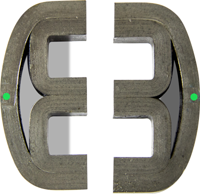
| E-core | Dmin*Emin*S | g*Acmin*(Amax+Bmax+2Fmin+2Gmin-0.074Emax-2.58Rmax)* 10-3 | |
| Toroid | (p/2)* (ODmax+IDmin) | Dmin*Emin*S | Ac min*Lm*g*10-3 |
Notes:
- A, B, D, E, F, G, R, OD, ID
- g-material density (7.65 gr/cm³),
- S-space factor
The numerical values of Lm, Ac and Wt, calculated from the above for our standard cores can be seen in Section C.
V=4.44*f*Bm*Ac*N*10-6
Where:
V = R.M.S. voltage;
f = Frequency ( Hz),
Bm = Maximum magnetic induction (Tesla),
Ac min = Effective cross sectional area (mm2),
N = Number of turns.
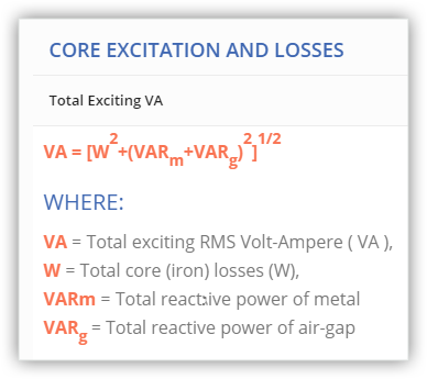
CORE EXCITATION AND LOSSES
VA = [W2+(VARm+VARg)2]1/2
Where:
VA = Total exciting RMS Volt-Ampere ( VA ),
W = Total core (iron) losses (W),
VARm = Total reactגive power of metal
VARg = Total reactive power of air-gap
Note:
Total exciting power (VA) may be briefly calculated by multiplying the core weight by
the guaranteed specific exciting power (VA/kg).
P=W/kg*Wt min*10-3
Where:
P = Total core (iron) loss ( W),
W/kg = Specific core loss,
Wt min = Weight of the core (gr).
VARm=VARm/kg*Wt min*10-3
Where:
VARm/kg = Specific reactive power of metal
Wt min = Weight of the core (gr).
VARg = VARg/kg*Wt min*10-3
Where:
VARg/kg = Specific reactive power of air-gap,
Wt min = Weight of the core (gr).
| VARg/kg = | Bm2*f*a*104 4*g*Lm |
Where:
VARg/kg = Specific reactive power of air-gap,
Bm = Maximum induction ( Tesla),
f = Frequency ( Hz),
Ac min = Frequency ( Hz),
a = Mean flux path length of two gaps (mm),
g = Material density ( 7.65 gr/cm3),
Wt.min = Weight of the core (g).
POWER HANDLING CAPACITY
Power handling capacity of magnetic cores is affected by the required regulation, copper space factor and temperature rise limit. The permissible temperature rise depends upon current density, flux density, frequency, class of insulation, duty cycle and the heat dissipation capability of the transformer. That is why power rating cannot be specified precisely. The power handling capacity of the magnetic cores may be determined from Eq.B.5.4.2-B.5.4.3, using the following values:
| Core weight, gram | Current density, A/mm² |
|---|---|
| 0-3500 | 3.1 |
| 3500-10000 | 2.0 |
| 10000-50000 | 1.5 |
| 50000-60000 | 1.0 |
Notes:
- A, B, D, E, F, G, R, OD, ID
- g-material density (7.65 gr/cm³),
- S-space factor
The numerical values of Lm, Ac and Wt, calculated from the above for our standard cores can be seen in Section C.
VA=5.0*J*Bm*f*Ac min*ID²*10-7
Where:
VA = Power handling capacity (VA),
J = Current density (A/ mm2),
Bm = Maximum magnetic induction (Tesla),
f = Frequency ( Hz),
ID = Inside diameter (mm),
Bc min = Effective cross sectional area (mm2)
VA=7.0*J*Bm*f*GF*Ac min*10-7
Where:
VA = Power handling capacity (VA),
J = Current density (A/ mm2),
Bm = Maximum induction (Tesla),
f = Frequency ( Hz),
GF = Window area (mm2),
Ac min = Effective core cross section) (mm2).
| VARg/kg= | 2.5*Bm2*f*a*Acmin Wtmin |
The modification of wound cores (cut or uncut) to special size and shape requirements is much easier when compared to the expensive process of punching new lamination shapes. Determine the core dimensions either by using equation B.5.4. or by other considerations. Note that a square core cross section (D=E) will result in the minimum mean length of turn of copper wire. It must further be noted, however, that since the induction is in inverse ratio to path length (Bm »1/Lm), a large difference between inside (window) core path length and outside (overall) path length will result in premature saturation of the inner wraps of the core. It is therefore desirable to minimize the difference between the outside and inside path lengths.
TOROIDS
The un-bonded uncut toroid is near-perfect magnetic loop. It preserves virtually all the basic material properties. This minimizes losses and decreases the magnetizing force necessary to produce a given flux within the material. In the toroid and coil assembly, the entire magnetic path is contained within the electrical winding, further minimizing leakage flux and increasing winding-to-winding coupling. The toroid also provides a good degree of self-shielding from external magnetic fields. The single, uniform, magnetic path causes any entering magnetic field to split into two and induce equal but opposite voltage in the two halves of a uniformly distributed winding. Thus, they tends to be no voltage apparently induced in the total winding.
| Outside diameter OD (mm) | Allowable tolerances (mm) | ||
|---|---|---|---|
| Outside diameter OD | Inside diameter ID | Strip width H | |
| 35÷50 | ± 1.0 | ± 0.5 | + 0.6 |
| 50÷80 | ± 1.25 | ± 0.75 | + 0.8 |
| 80÷100 | ± 1.5 | ± 1.0 | + 1.0 |
| 100÷160 | ± 2.0 | ± 1.3 | + 1.5 |
| 160÷200 | ± 2.5 | ± 1.5 | + 1.5 |
| 200÷340 | ± 3.0 | ± 2.0 | + 2.0 |
PULSE CORES
Typical pulse permeability using DC-reset and a flux change of ΔB=2.2 Tesla for 0.05mm material, and ΔB=2.8 Tesla for 0.10mm material is shown in D.11. These curves can also be used for pulse cores having an air-gap reset. In this case the pulse permeability is 60% of the value shown for a flux change ΔB=1.0 Tesla for 0.05mm and ΔB=1.5Tesla for 0.10mm material.
| mp = | ΔB*Lm*104 4*π*N*Im |
Where:
mp = Pulse permeability,
ΔB = Induction change (Tesla),
Lm = Mean length of core (mm),
N = Peak exciting current (Amperes).
Im
U*t = N*Ac min*ΔB*10-6
Where:
U = Peak pulse voltage (Volts),
t = Pulse length (seconds),
N = Number of primary turns,
Ac min = Effective cross sectional area (mm2),
ΔB = Induction change (Tesla),

Contact Us:
- Eilor Ltd.
- +972 (8) 6358601
- eilor-office@eilor.co.il
© 2022 - Eilor magnetic cores | Website by moostash