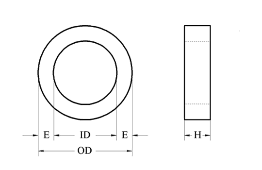
METRIC STANDARDS
| Allowable tolerances (mm) | |||
|---|---|---|---|
| Outside diameter | Outside diameter | Inside diameter | Strip width |
| OD (mm) | OD | ID | H |
| 35-50 | ± 1.0 | ± 0.5 | + 0.6 |
| 50-80 | ± 1.25 | ± 0.75 | + 0.8 |
| 80-100 | ± 1.5 | ± 1.0 | + 1.0 |
| 100-160 | ± 2.0 | ± 1.3 | + 1.5 |
| 160-200 | ± 2.5 | ± 1.5 | + 1.5 |
| 200-340 | ± 3.0 | ± 2.0 | + 2.0 |
Note:
The tolerances are given for uncut toroids.
For cores with E£10mm
The diameter tolerances rise by +0.3mm.
The shape of toroids after cutting is ovalized.
Electrical Guarantees
Guaranteed magnetic properties of annealed non-impregnated toroids are corresponded to standard limiting properties for a used grades of grain-oriented silicon steel.
Note:
For steel thickness 0.30-0.35 mm it is correct only for toroids with inner diameter greater than 30mm and strip width greater than 10mm; For steel thickness 0.10mm correspondent requirement -inner diameter >10mm and width >4mm.
In epoxy coated or impregnated toroids magnetic degradation is occurred due to mechanical stresses.
In these toroids the core losses are increasing approximately by 20-30% in comparison with raw material.

GRAIN-ORIENTED ELECTRICAL STEEL
AVAILABLE GRADES AND GUARANTEED SPECIFIC LOSSES
| Thickness,mm (inch) | Grade, according to | Maximum specific core losses, W/kg, at | Stacking Factor(min) | ||||
|---|---|---|---|---|---|---|---|
| AISI | IEC 604048-8-7 | EN 10303 | 1.7T/50Hz | 1.5T/400Hz | 0.5T/2000Hz | ||
| 0.30(0.012) | M-5 | M 140-30 | – | 1.40 | – | – | 0.95 |
| M0-H | M 105-30 | – | 1.05 | – | – | ||
| 0.27(0.011) | M4 | M 130-27 | – | 1.30 | – | – | |
| M0-H | M 100-27 | – | 1.00 | – | – | ||
| 0.23(0.009) | M3 | M 120-23 | – | 1.20 | – | – | 0.94 |
| M0-H | M 090-23 | – | 0.90 | – | – | ||
| 0.10(0.004) | – | – | GO 10 | – | 15.0 | – | 0.92 |
| 0.05(0.002) | – | – | GO 5 | – | – | 15* | 0.89 |
Note:
Density=7.65 g/cm3
*- not guaranteed


